Introduction / はじめに
The soil structure interaction of buried pipelines in liquefiable soils during earthquake shakings is studied using the shaking table apparatus. The research is mainly focused on the uplift of the structure for different shaking stages.
振動台試験機を用いて,液状化地盤中における埋設物に関して,地盤-構造物相互作用を検討する.本研究では,特に,液状化時の埋設物の浮き上がり挙動に着目する.
Preparation of the model / 地盤モデルの作製
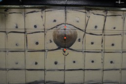
In a rigid soil container, 260 cm long, 60 cm high and 40 cm deep, the soil deposit is prepared using Silica Sand n. 7 with a relative density of 55%. A 40 cm long PVC pipe with a nominal diameter of 100 is buried at 13.6 cm from surface to the top of the pipe. The model scale is 1:10. It is prepared filling the soil box with dry sand, through the air pluviation method using a sand hopper, and saturated from the bottom with a hosepipes infiltration system delivering water at very low pressures. The water level in the soil box is controlled with piezometers. Pore water pressure sensors and accelerometers are set at different depths in the soil deposit, both close to the pipe and in the free-field area (Figure 1).
振動台試験機を用いて,液状化地盤中における埋設物に関して,地盤-構造物相互作用を検討する.本研究では,特に,液状化時の埋設物の浮き上がり挙動に着目する.モデル地盤は,剛土槽(幅x奥行x高さ:260cm x 60cm x 40cm)に7号珪砂を相対密度55%で作成した.埋設物モデルは,直径10cm,奥行40cmの塩ビパイプを表層から深さ13.6cmの高さ(パイプの頂点)に設置した.モデルスケールは実モデルの1/10を想定している.気中落下で乾燥地盤を作成し,その後,土槽下部から徐々に水を供給し,水位を上げていくことで飽和地盤を作成する.ピエゾメータの値を見ながら,地盤内水位を調整する.図1に示すように,間隙水圧計,加速度計をモデル地盤の各地点に設置する.
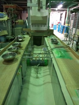
Figure 1. Preparation of the model: sand hopper and installation of the pipeline and sensors
Complete model / 実験模型
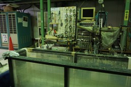
These transducers are used to study the response of the model, monitor the liquefaction stage and compute the shear stresses and shear strains. To evaluate the vertical displacements of the pipe and of the ground surface, laser sensors are installed. With a mounting bracket attached to the shaking table, a high-speed and high-resolution camera is fixed in front of the face of the box (Figure 2).
モデル地盤は,剛土槽(幅x奥行x高さ:260cm x 60cm x 40cm)に7号珪砂を相対密度55%で作成した.埋設物モデルは,直径10cm,奥行40cmの塩ビパイプを表層から深さ13.6cmの高さ(パイプの頂点)に設置した.モデルスケールは実モデルの1/10を想定している.気中落下で乾燥地盤を作成し,その後,土槽下部から徐々に水を供給し,水位を上げていくことで飽和地盤を作成する.ピエゾメータの値を見ながら,地盤内水位を調整する.図1に示すように,間隙水圧計,加速度計をモデル地盤の各地点に設置する.これらの計測機器を使用して,モデル地盤の挙動,特に液状化程度,応力-ひずみ関係を観測する.地盤の沈下量ならびに埋設物の浮き上がりを計測するため,レーザー変位計をモデル外部に設置する.また高解像度カメラによって,地盤内挙動の画像解析も行う(図2)
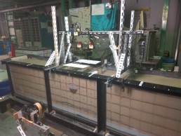
Figure 2. Complete model, installation of laser sensors and camera
Test Results / 実験結果
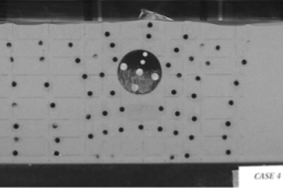
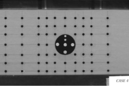
The photos taken are used to continuously measure the movement of the sand particles in the area close to the pipe. Two symmetrical loops have been observed, forming from the top of the pipe to the bottom part on both sides of the structure (Figure 3).
写真から,パイプが上昇するとともに,周辺の砂はパイプ周りを上から下に回り込むように移動している様子が確認できる.
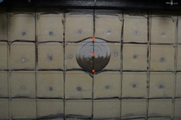
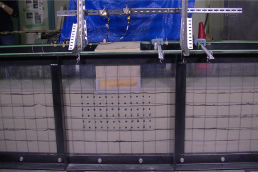
Figure 3(a). Before Shaking